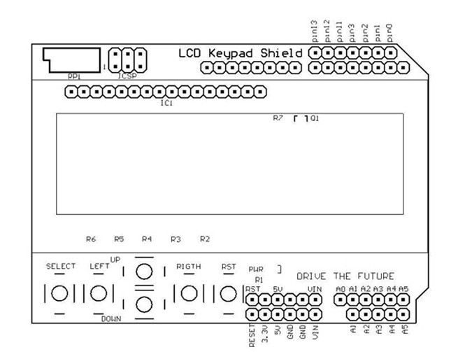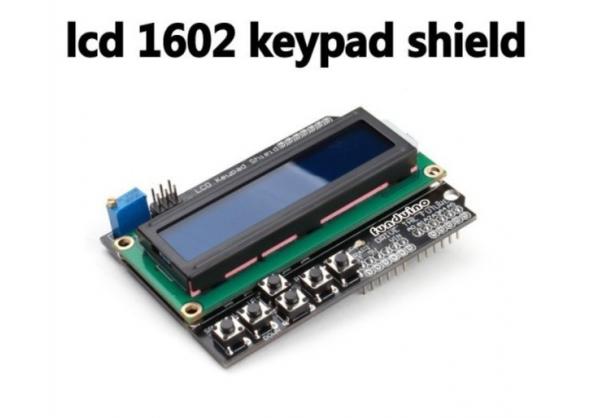
The VSS power ground 9 D2 data
2 VDD positive power supply 10 D3 data
3 VL LCD bias
4 RS data / command select 12 D5 data
5 R / W read / write select 13 D6 data
6 E enable signal
7 D0 data the 15 BLA backlight source positive
8 D1 data the 16 BLK backlight negative
1 foot: VSS ground power.
2 feet: VDD connected to the the 5V positive supply.
3 feet: VL for the LCD display contrast adjustment terminal connected to the positive power supply contrast weakest ground when contrast
Highest contrast is too high will produce " ghosting " , used by a 10K potentiometer to adjust the contrast.
4 feet: RS register select, select the data register, high and low, select the instruction register.
5 Foot: R / W for read and write signal line, a high read operation, the low write operation. When RS
and R / W can be written instructions or display the address, when RS for the low-levelR / W
Busy signal can be read, when RS high R / W is low can be written.
6 feet: E -side to enable end, When E Duanyou high jump goes low, the LCD module execute command.
7 to 14 feet: D0 to D7 for 8 -bit bi-directional data line.
15 feet: backlight positive.
16 feet: backlight negative.
The 1602LCD the instruction descriptions:
1602 LCD module within the controller 11 control instructions, such as table shown in the table below:
The serial directive RS R / W D7 D6 D5 D4 D3 D2 D1 D0
1 0 0 0 0 0 0 0 0 0 1
2 cursor returns 000,000,001 *
3 set the input mode 0 0 0 0 0 0 0 1 I / DS
4 display on / off control 0 0 0 0 0 0 1 DCB
5 cursor or character shift 0 0 0 0 0 1 S / CR / L **
6 set function 0 0 0 0 1 DL NF **
7 set character generator memory address 0001 character generator memory address
8- position data memory address 001 to display the data memory address
9 read busy flag or address 0 1 BF counter address
10 write the number to CGRAM or DDRAM ) 1 0 write data content
11 from CGRAM or DDRAM readings
1602 LCD module of read and write operations, the operation of the screen and the cursor are achieved through instruction programming. (Note: a high, 0 low)
Directive 1 : clear script 01H, the cursor reset to address 00H position.
Directive 2 : Cursor reset, the cursor returns to the address 00H .
Directive 3 : cursor and display mode settings I / D : Move the cursor direction, high to the right, low level the left S:
All the text on the screen whether the left or the right. High indicates low invalid.
Instruction : display switch control. D : control the overall display on and off, the high indicates open display, low power
Level expressed concern C : control the cursor on and off high indicates cursor low no cursor B : control
Made whether the cursor is flashing, high flash, low level does not blink.
Directive 5 : cursor or display shift S / C : high mobile display text, low, move the cursor.
Directive 6 : function set command DL : high 4 -bit bus , low level
Usually displayed as a single line, two-line display high
5x10 dot matrix characters.
Directive 7 : character generator RAM address set.
Directive : the DDRAM address setting.
Directive 9 : read a busy signal and cursor address BF : busy flag high indicates busy, the module can not be connected
Received command or data, if is low is not busy.
Directive 10 : write data.
Instruction 11 : read data.
with the HD44780 chip timing table is as follows:
Read Status input RS = L , R / W = H , E = H outputs D0 - D7 = Status Word
Write command input RS = L , R / W = L , D0 - D7 = no
Read data entry RS = H , R / W = H , E = H output D0 - D7 = data
Write data input RS = H , R / W = L , D0 - D7 = Data, E = high pulse output No
1602LCD general initialization (reset) process:
Delay 15mS
Write instruction 38H (does not detect a busy signal)
Delay 5mS
Write instruction 38H (does not detect a busy signal)


