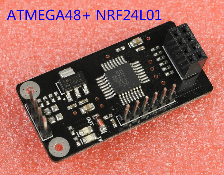
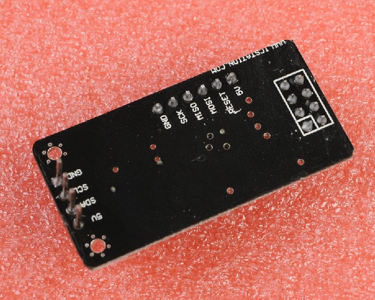
Ⅰ module features:
1 ) using I2C (TWI) communication protocol , which greatly simplifies the communication process NRF24L01 of
Users do not need to know NRF24L01 cumbersome communication process , greatly improving the project development
Efficiency.
2 ) Each module is as I2C (TWI) slave ( address 35 )
3 ) small and long 73mm wide 22mm module
4 ) smooth two-way communication , regardless of the slave and master.
5 ) The maximum transmission distance can reach 70m ( only for production test )
6 ) wireless communication chip NRF24L01 reliable communication protocol , reducing data loss
7) I2C/TWI protocol greatly simplifies the communication lines,
8 ) perfectly compatible with arduino
. Ⅱ applications:
Robot control , remote control . Information collection , etc.
Note : The wireless communications may have radiation , not recommended for protection of life .
Ⅲ. Related parameters
Operating voltage : 5V, no short circuit protection , the use must be careful not to reverse polarity .
Weight : 6g
Module receives the data hold time : more than 2S
Module sends data hold time : more than 300s
Transfer rate : 50Byte / S ( theoretical value )
I2C/TWI Address : 0x47 ( decimal 35 )
NRF24L01 Address : 0x34, 0x43, 0x10, 0x10, 0x01 ( low to high )
Related terms:
Will transmit the transmission data holding means when the module (TWI slave ) receives the data transmitted from the host to another data module, and then waits to receive another response signal of a module , and then wait for a period of time if either no acknowledge signal then data module will re-send the data out , multiplied by the number of repeat sending data latency is the module sends the hold time
Immediately module receives data hold time is when module (TWI slave ) receives the transmitted data NRF24L01 after shielding NRF24L01, the system jumps to wait for the host to take over the data , the maximum waiting time is receiving data hold time
Ⅳ test compatible devices
Model 1 Model 2

The maximum
transmission 70m 100m
distance (open) :
Ⅴ. Mechanical Drawings
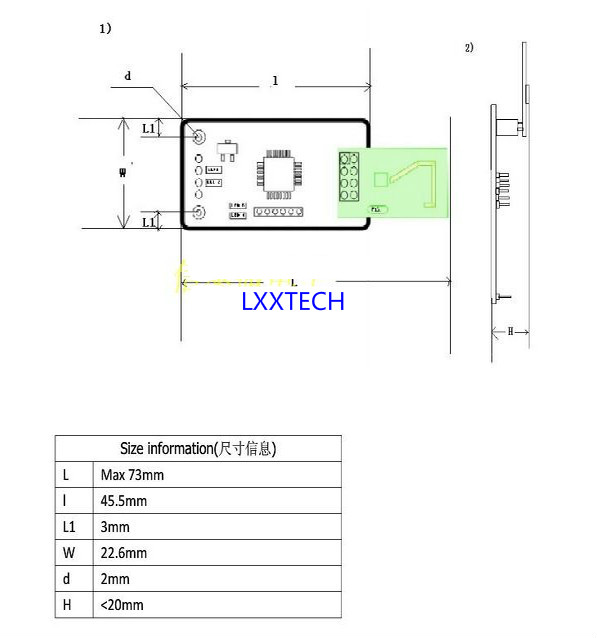
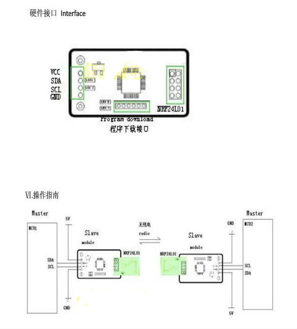
Ⅵ. Operations Guide
This module uses a I2C/TWI communication, using NRF wireless communication module , secure and reliable data greatly reduces the total loss of the three states in the communication process :.. MCU read data , free mode (MCU write data or NRF24L01 write data ) module is busy ( module sends data ) .
1) MCU read data state is , MCU module reads the data for the state, then the module receives the data sent over NRF24L01 and save up, wait for the host to read ( module LED IN lights )
Note : Read data state shield NRF24L01, that it can not carry out any operation NRF24L01 read data while the state has a data retention time , if more than the hold time yet to read the data host , the module automatically jump to the free mode .
2 ) free mode (MCU NRF24L01 write data or write data ) means : NRF24L01 module and the host (TWI/I2C) can only write to it (LED OUT / IN are off ) .
Jump to the following modules may free mode :
1 module sends data to reach the maximum number of
2 module was successfully sent data
3. MCU receives data from the module to the
4 free state beyond the hold time
3) The module is busy state, when the host module receives the data transmitted , the module jumped busy state , and periodically sends a data block to another while waiting for the other module transmits a response signal if after a period of time ( block send data hold time ) then there is no answer , he served as the data , the module automatically jump to the free mode . If you receive a response signal . modules can also jump to the free mode . ( module LED OUT lights )
1 reads the data format :
MCU Module address to send a response if the module generates the data returned is not "0X47", then read the data to prove successful .
Only read one byte of data
2 write data format
MCU address and sends the data transmission module , each can only send one byte of data and then generate a stop bit. If the module is busy, you need to re-send the
Note : When the module is idle host read data is always read results are 0x47
Receive data when the MCU must filter out 0x47 ( decimal 71 ) , otherwise the program will go wrong
