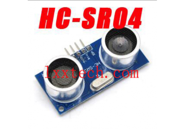
Module main technical parameters:
1.Working Voltage : 5V(DC)
2.Static current: Less than 2mA.
3.Output signal: Electric frequency signal, high level 5V, low level 0V.
4.Sensor angle: Not more than 15 degrees.
5.Detection distance: 2cm-450cm.
6.High precision: Up to 0.3cm
7.Input trigger signal: 10us TTL impulse
8.Echo signal : output TTL PWL signal
Mode of connection:
1.VCC
2.trig(T)
3.echo(R)
4.GND
Use method:
Product feature:
HC-SR04 ultrasonic module can offer non-contact distance sensing function, the range of which is 2cm¡ª400cm., and the range accuracy is up to 2mm; the module includes ultrasonic transmitter, receiver and control circuit.
The basic operation principle is below:
use IO port TRIG to trigger ranging. It needs 10 us high level signal at least
Module can send 8 pro 40 kz square wave automatically, and will test if there is any signal returned.
If there is signal returned, output one high level signal via IO port ECHO. The duration of the high level signal is the time from transmitter to receiving with the ultrasonic.
Testing distance =duration of high level*sound velocity(340m/s) / 2
Physical map
Refer to the wiring diagram below,
VCC supply 5V, and GND is ground wire. TRIG is trigger control signal input, ECHO is echo signal output.
electric parameter:
|
Electric parameter
|
HC-SR04 ultrasonic module
|
|
Operating voltage
|
DC 5V
|
|
Operating current
|
15 mA
|
|
Operating frequency
|
40 Hz
|
|
Utmost range
|
4 m
|
|
Nearest range
|
2cm
|
|
Measure angel
|
15 ¡ã
|
|
Input trigger signal
|
10uS TTL pluse
|
|
Output echo signal
|
Output TTL level signal, proportional to the range
|
|
specification
|
45*20*15 mm
|
Ultrasonic sequence diagram:
trigger signal

Sending signal inside the module

Output echo signal

Picture1: Ultrasonic sequence diagram
The sequence diagram above indicates that you just need to supply one 10 uS pulse or above to trigger the signal, inside the module, it will send 8 pro 40kHz round electric level with testing the returning wave. Once tested that there is returning wave signal, then it will output echo signal. The pulse width of the echo signal is in direct proportion to the testing distance. Therefore, the distance can be caculated according the duration from the sending signal to receiving signal.
Here is the formula below:
uS/ 58=cm or uS/148=inch; distance=high level time*sound velocity(340m/s) / 2
Suggestion: the measurement period is 60ms or above, which can protecting echo signal from sending signal.
Note:
(1). for this module, keep in mind not to connect with electricity. If it is connected with electricity, you need to connect up the GND port of the module firstly, otherwise it will affect the normal working of the module.
(2). When testing, the coverage of the tested object is 0.5 square meter or below, and try to make the plate smoothly., otherwise, it will affect the result of the testing.
Specification of the object.:


