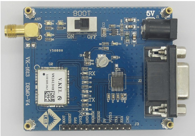
VK1613HX GPS Test Board
Product description :
The new VK1613HX development board, using a common pin 2.54mm pitch leads to common IO convenient secondary development , an increase of four positioning holes to facilitate customers to develop integrated mounting plate located on your motherboard , and increases the second pulse output and display , can be judged by the onboard LED positioning status (PPS or the LED blinks GPIO14 that successful positioning ) and other features, the use of imported industrial grade 232 converter chip , MAX3221IPWR
1 using high sensitivity SiRFIII low-power chip , built-in high gain LNA,, Dual LDO, better and more stable signal . With selectable baud rate and so on 4800,9600,19200,38400,5700,115200 RMC, GSV, GSA, GGA, VTG, GLL and other statements that can be freely combined to make your job easier microcontroller .
2 Development Board is entirely export products and accessories , all components on the board are industrial temperature range
3 . Enterprise customers to order our products , the company will provide professional technical support and GPS services .
4 Our product positioning faster, stronger signal , higher accuracy, the interface is more complete, better service , large price better . Our understanding of the GPS , our profession, our technology, our products, our quality , we must make you satisfied !
Features:
● high-precision , high-performance GPS receiver module
● with a rechargeable battery backup can be achieved quickly locate hot start 1 second
● TTL level interface for easy connection to a variety of processors
● Built-in RS232 level serial port for easy connection to a computer , with a professional GPS test software
● Mini USB to TTL with cable, can be powered by USB , Direct Connect Computer Test
● Support 3.3V power output or input , easy -powered microcontroller development board
● Power , TX, RX data , BOOT, PPS indicator
● Common IO convenient secondary development leads
1,3 feet DC power seat 5v DC input voltage requirement
2, AMS1117 transformer IC to 5V input voltage into 3.3V
3, P07: 700MA automatic recovery fuse, when the lines when the current is higher than 700MA , P07 will automatically disconnect an external 5V DC power supply , the current transmission is restored to normal , all the components can be well protected good development board .
4, MAX3221 chip : TTL signal modules and 232 signal converter
5 , burned into the switch: When the switch backward BOOT pin when the module stops working , burned into the program and into the state . ( Note: The first time the switch backward burned into the BOOT pin and then plug in the power )
6 , rechargeable 3.3v lithium coin battery: battery module pin provides a voltage , so that modules can be hot-start
7 , the power indicator : just plug the external 5v DC power supply, or usb power, the power will light
8 , burned into the Signal Indicator: This indicator will light when the switch is backward when BOOT
9, PSS Indicator : This indicator flashes when the module positioning ( with burned into the procedures )
10, GPIO14 Indicator : This indicator flashes when the module positioning ( with burned into the procedures )
11: TXD signal indicator : when the module indicator lights
RXD signal indicator : module burned into the program when the indicator lights
PCB size : 66mm × 55mm × 1.6mm


